pin diagram explanation for Arduino
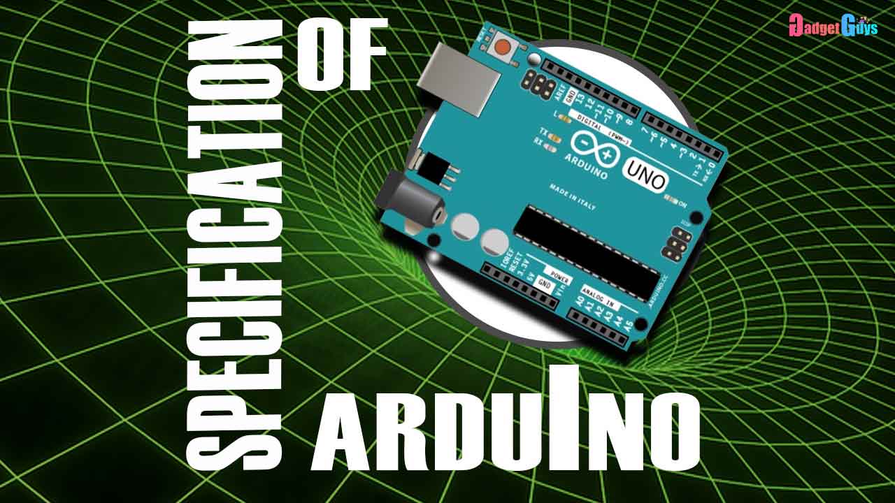
let’s see the features of the Arduino Uno board and the pin details .The latest Arduino Uno uses an atmega328 microcontroller which is manufactured by Atmel, giving you input voltage of around 7 volt or 12 volt to this port. the operating voltage of the microcontroller is 5 volt.

It has a CPU speed of 16 megahertz there are analog input or output pins which is in 6 in number there are the 14 digital input/output pins out of which 6 can be used for pulse width modulation.
The major feature of this pulse width modulation is ,it can be used to vary the intensity or the speed it has a BP room of 1 kb SRAM of 2 kb flash memory of 32 kb, which can be used to store the program or load the program .
universal asynchronous receiving transmission of 1 USB type is regular it has a reset pin which when pressed the program is going to start from the first line the pin numbers are 4 and a 5 which are analog pins has SDA and a CL input ,which can be used to receive a real-time clock configuration .
The digital pins 0 and 1 are used for serial communication 0 for receiving and 1 for transmission pin number 2 and 3 which is digital can also be used for interrupts purpose .
